• Vision
  • About us
  • RedCap in 5G

    Joni Tyagi

    Definition of RedCap UE

    A RedCap UE has reduced capabilities with the intention to have lower complexity with respect to non-RedCap UEs RedCap UE is the UE with reduced capability:
    - The maximum bandwidth is 20 MHz for FR1 and is 100 MHz for FR2. UE features and corresponding capabilities related to UE bandwidths wider than 20 MHz in FR1 or wider than 100 MHz in FR2 are not supported by RedCap UEs;
    - The maximum mandatory supported DRB number is 8;
    - The mandatory supported PDCP SN length is 12 bits while 18 bits being optional;
    - The mandatory supported RLC AM SN length is 12 bits while 18 bits being optional;
    - For FR1, 1 DL MIMO layer if 1 Rx branch is supported, and 2 DL MIMO layers if 2 Rx branches are supported;
    for FR2, either 1 or 2 DL MIMO layers can be supported, while 2 Rx branches are always supported. For FR1 and FR2, UE features and corresponding capabilities related to more than 2 UE Rx branches or more than 2 DL MIMO layers, as well as UE features and capabilities related to more than 1 UE Tx branch, or more than 1 UL MIMO layer are not supported by RedCap UEs;
    - CA, MR-DC, DAPS, CPAC and IAB (i.e., the RedCap UE is not expected to act as IAB node) related UE features and corresponding capabilities are not supported by RedCap UEs. All other feature groups or components of the feature groups as captured in TR 38.822 [24] as well as capabilities specified in this specification remain applicable for RedCap UEs same as non-RedCap UEs, unless indicated otherwise.

    General parameters

    ncd-SSB-ForRedCapInitialBWP-SDT-r17

    Indicates that the UE supports using RedCap-specific initial DL BWP associated with NCD-SSB for SDT. If absent, the UE only supports SDT in an initial DL BWP that includes the CD-SSB. UE supporting this feature shall indicate support of supportOfRedCap-r17 and ra-SDT-r17 and/or cg-SDT-r17.

    supportOf16DRB-RedCap-r17

    Indicates whether the RedCap UE supports 16 DRBs. This capability is only applicable for RedCap UEs.

    supportOfRedCap-r17

    Indicates that the UE is a RedCap UE with comprised of at least the following functional components:
    - Maximum FR1 RedCap UE bandwidth is 20 MHz;
    - Maximum FR2 RedCap UE bandwidth is 100 MHz;
    - Support of RedCap early indication based on Msg1, MsgA (if UE indicated support of twoStepRACH-r16) and Msg3 for random access;
    - Separate initial UL BWP for RedCap UEs;
    - It includes the configuration(s) needed for RedCap UE to perform random access
    - Enabling/disabling of frequency hopping for common PUCCH resources
    - Separate initial DL BWP for RedCap UEs;
    - It includes CSS/CORESET for random access
    - For separate initial DL BWP used for paging, CD-SSB is included
    - For separate initial DL BWP only used for RACH, SSB may or may not be included
    - For separate initial DL BWP used in connected mode as BWP#0 configuration option 1, CD-SSB is included
    - 1 UE-specific RRC configured DL BWP per carrier;
    - 1 UE-specific RRC configured UL BWP per carrier;
    - UE-specific RRC-configured DL BWP with CD-SSB or NCD-SSB;
    - NCD-SSB based measurements in RRC-configured DL BWP.
    A RedCap UE shall set the field to supported.

    PDCP parameters

    longSN-RedCap-r17

    Indicates whether the RedCap UE supports 18-bit length of PDCP sequence number. This capability is only applicable for RedCap UEs.

    RLC parameters

    am-WithLongSN-RedCap-r17

    Indicates whether the RedCap UE supports AM DRB with 18-bit length of RLC sequence number. This capability is only applicable for RedCap UEs.

    MeasAndMobParameters

    rrm-RelaxationRRC-ConnectedRedCap-r17

    Indicates whether UE supports Rel-17 relaxed RRM measurements in RRC_CONNECTED as specified in TS 38.331 [9].

    Physical layer parameters

    BandNR parameters
    bwp-WithoutCD-SSB-OrNCD-SSB-RedCap-r17

    Indicates support of RRC-configured DL BWP without CD-SSB or NCD-SSB. The UE can include this field only if the UE supports supportOfRedCap-r17.

    halfDuplexFDD-TypeA-RedCap-r17

    Indicates support of Half-duplex FDD operation (instead of full-duplex FDD operation) type A for RedCap UE. The UE can include this field only if the UE supports supportOfRedCap-r17.

    Identification, access and camping restrictions

    - A RedCap UE can be identified by the network during Random Access procedure via MSG3/MSGA from a RedCap specific LCID(s) and optionally via MSG1/MSGA (PRACH occasion or PRACH preamble). For RedCap UE identification via MSG1/MSGA, RedCap specific Random-Access configuration may be configured by the network.
    - For MSG3/MSGA, a RedCap UE is identified by the dedicated LCID(s) indicated for CCCH identification (CCCH or CCCH1) regardless of whether RedCap specific Random-Access configuration is configured by the network.
    - RedCap UEs with 1 Rx branch and 2 Rx branches can be allowed separately via system information. In addition, RedCap UEs in Half-Duplex FDD mode can be allowed via system information. 
    - A RedCap specific IFRI can be provided in SIB1, when absent, RedCap UEs access is not allowed. Information on which frequencies RedCap UE access is allowed can be provided in system information.
    - A RedCap UE with 1 Rx branch applies the associated offset for broadcasted cell specific RSRP thresholds for random access, SDT, cell edge condition and cell (re)selection criterion as specified in TS 38.133 [13].
     
    NOTE: It is up to the E-UTRA network, if possible, to avoid handover attempts of a RedCap UE to a target NR cell not supporting RedCap. It is up to the RedCap UE implementation, if possible, to recover from handover attempts to a target NR cell not supporting RedCap.

    RRM measurement relaxations

    RRM measurement relaxation is enabled and disabled by the network. In RRC_IDLE and RRC_INACTIVE a RedCap UE is allowed to relax neighbor cell RRM measurements when the stationary criterion is met or when both stationary criterion and not-at-cell-edge criterion are met. Network may configure stationary criterion for a RedCap UE in RRC_CONNECTED and the UE reports its RRM measurement relaxation fulfilment status using UE Assistance Information when the stationarity criterion is met or no longer met.

    BWP operation

    A RedCap UE in RRC_IDLE or RRC_INACTIVE monitors paging only in an initial BWP (default or RedCap specific) associated with CD-SSB and performs cell (re-)selection and related measurements on the CD-SSB. If a RedCap specific initial UL BWP is configured and NUL is selected, RedCap UEs in RRC_IDLE and RRC_INACTIVE shall use only the RedCap-specific initial UL BWP to perform RACH.
     
    A RedCap UE may be configured with multiple NCD-SSBs provided that each BWP is configured with at most one SSB. NCD-SSB may be configured for a RedCap UE in RRC_CONNECTED to perform RLM, BFD, and RRM measurements and RA resource selection when the active BWP does not contain CD-SSB.

    NR RedCap UEs differentiation

    - This functionality is used by the network to identify traffic to/from UEs accessing over NR RedCap, e.g. for charging differentiation.
    - An NR RedCap UE using NR shall provide an NR RedCap indication to the NG-RAN during RRC Connection Establishment procedure as defined in TS 38.300 [27].
     
    - When the UE has provided an NR RedCap indication to the NG-RAN during RRC Connection Establishment, the NGRAN shall provide an NR RedCap Indication to the AMF in the Initial UE Message (see clause 4.2.2.2.1 of TS 23.502 [3] and TS 38.413 [34]).

    - When the AMF receives an NR RedCap Indication from NG-RAN in an Initial UE Message, the AMF shall store the NR RedCap Indication in the UE context, consider that the RAT type is NR RedCap and signal it accordingly to the SMSF during registration procedure for SMS over NAS, to the SMF during PDU Session Establishment or PDU Session Modification procedure. The PCF will also receive the NR RedCap RAT type indication when applicable, from the SMF during SM Policy Association Establishment or SM Policy Association Modification procedure.

    - During handover from E-UTRA to NR, the target NG-RAN (i.e. gNB) provides the NR RedCap indication to AMF in NGAP Path Switch Request message during Xn handover, or NGAP Handover Request Acknowledge message during N2 handover (including intra 5GS N2 handover and EPS to 5GS handover) based on the UE capability information provided by the source RAN to the target RAN as specified in TS 38.300 [27].

    - The NFs interacting with CHF shall include the NR RedCap as RAT type Upon AMF change, the source AMF shall provide the "NR RedCap Indication" to the target AMF.

    5G NR Measurement Events & Signaling events

    Joni Tyagi

    About 5G NR Measurement Events :

    The events are defined in 3GPP TS 38.331 for NR and TS 36.331 for LTE used to make sure efficient mobility management and handover management in 5G and 4G networks. 

    These events are used to trigger specific actions and procedures in user equipment (UE) and the network when certain conditions are met. 

    By doing so, the network can ensure seamless connectivity and optimal performance for mobile devices as they move within the coverage area.

    The events are defined in TS 38.331 release 17 cover various scenarios, such as detecting when a UE moves towards the cell edge, identifying stronger neighboring cells, or determining the need for handover due to changing radio conditions and keep users experience reliable and high-quality connectivity while on the moving conditions. These events help in:

    Handover Optimization: 

    Ensuring that a UE is handed over to a different cell or frequency when the current connection quality degrades, thereby maintaining a stable and uninterrupted service.

    Radio Resource Management: 

    Efficiently managing radio resources by triggering measurements and mobility procedures only when necessary, reducing unnecessary signaling and network load.

    Seamless Connectivity: 

    Enabling smooth and seamless transitions between different cells and frequencies, providing a consistent user experience during mobility.

    Network Efficiency: 

    Optimizing the network's performance by making intelligent decisions based on real-time radio conditions and user equipment capabilities.
    Event TypePurpose of events
    Event A1Serving becomes better than threshold
    Event A2Serving becomes worse than threshold
    Event A3Neighbour becomes offset better than SpCell
    Event A4Neighbour becomes better than threshold
    Event A5SpCell becomes worse than threshold1 and neighbour becomes better than threshold2
    Event A6Neighbour becomes offset better than SCell
    Event B1Inter RAT neighbour becomes better than threshold
    Event B2PCell becomes worse than threshold1 and inter RAT neighbour becomes better than threshold2
    Event I1Interference becomes higher than threshold
    Event C1The NR sidelink channel busy ratio is above a threshold
    Event C2The NR sidelink channel busy ratio is below a threshold
    Event D1Distance between UE and referenceLocation1 is above threshold1 and distance between UE and
    referenceLocation2 is below threshold2
    CondEvent T1Time measured at UE is within a duration from threshold
    Event X1Serving L2 U2N Relay UE becomes worse than threshold1 and NR Cell becomes better than threshold2
    Event X2Serving L2 U2N Relay UE becomes worse than threshold
    Event Y1PCell becomes worse than threshold1 and candidate L2 U2N Relay UE becomes better than threshold2
    Event Y2Candidate L2 U2N Relay UE becomes better than threshold

    SixG Introduction

    Joni Tyagi

    6G: Introduction

    6g introduction

    1. The Evolution of Wireless Connectivity

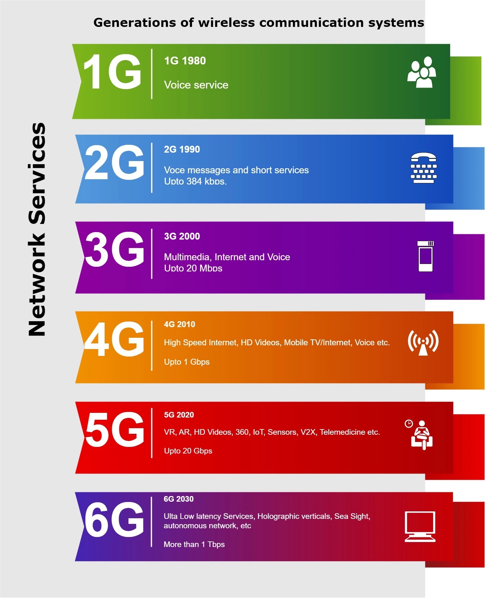
    First generation (1G):

    Mobile networks were designed for voice services with data rates of up to 2.4 kbit/s. Analog signals used to transmit information, and there was no universal wireless standard.

    Second generation (2G):

    Was based on digital modulation techniques and offered data rates of 50 Kbit/s to 384 Kbit/s, supporting not only voice services but also data services such as Short Message Service (SMS). The flagship 2G standard was the Global System for Mobile (GSM) communications.

    Third generation (3G):

    Mobile networks provided data rates of at least 2 Mbit/s and enabled advanced services including web browsing, TV streaming, and video services with data rates of up to 20 Mbit/s. To achieve global roaming, 3GPP was established to define technical specifications and mobile standards.

    Fourth generation (4G):

    Mobile networks were introduced in the late 2010s. 4G is an entirely Internet Protocol (IP) based network capable of providing high speed data rates of up to 1 Gbit/s in downlink and up to 500 Mbit/s in uplink to support advanced applications such as digital video broadcasting. DVB), high-definition TV content and video chat. LTE-Advanced (LTE-A) has been the dominant 4G standard, integrating technologies such as coordinated multipoint (CoMP) transmission and reception, multiple-input multiple-output (MIMO), and orthogonal frequency division multiplexing (OFDM).

    Fifth generation (5G):

    Is to use not only the microwave band but also the millimeter-wave (mmWave) band for the first time to significantly increase data rates to 20 Gbit/s. Another feature of 5G is the more efficient use of spectrum, as measured by increasing the number of bits per Hz. ITU's International Mobile Telecommunications 2020 (IMT 2020) standard proposed the following three major 5G usage scenarios:

    1. Enhanced Mobile Broadband (eMBB), 
    2. Ultra-Reliable and Low Latency Communications (URLLC),
    3. Massive Machine Type Communications (mMTC). 
    As 5G is entering the commercial deployment phase, research has begun to focus on 6G mobile networks, which are estimated to be deployed by 2030 Typically, next-generation systems do not emerge out of a vacuum, but rather follow industrial and technological trends from previous generations. Potential research directions for 6G in line with these trends were provided by Bi (2019), which included, among others:

    2. What is 6G?

    6G, short for the sixth generation of wireless technology, is envisioned to provide even faster data speeds, lower latency, greater capacity, and support for advanced technologies such as artificial intelligence, virtual reality, augmented reality, and the Internet of Things (IoT). It may also include innovations such as terahertz frequency bands, massive MIMO (multiple-input multiple-output) systems, and advanced antenna techniques to enhance network performance.
    ● 6G will continue to move to higher frequencies with wider system bandwidth: given that the spectrum at lower frequencies is nearly exhausted, the current trend is to increase the data rate by more than 10 times for each generation to achieve wider bandwidth at higher frequencies Is:
    Massive MIMO will remain a key technology for 6G: Massive MIMO has been the defining technology for 5G which has enabled the antenna count to increase from 2 to 64. Given that performance gains have saturated in the areas of the channel coder and modulator, spectral efficiency increases for 6G in the multiple antenna area will continue to be expected. MIMO Interview Questions Answers.
    6G will take cloud service to the next level: With consistently higher data rates, lower latency, and lower transmission costs, many computational and storage functions have been moved from smartphones to the cloud. As a result, most of a smartphone's computational power can be focused on presentation rendering, making VR, AR or XR more efficient and affordable. Many Artificial Intelligence (AI) services that are intrinsically cloud based can be more easily and widely proliferated. In addition to smartphones, low-cost functional terminals may once again flourish, providing opportunities for development in more application areas.
    Grant-free broadcasts may become more prominent in 6G: In previous cellular network generations, broadcasts were primarily based on grant-oriented designs with strong centralized system control. 6G will require more advanced grant-free protocols and approaches. It is possible that non-orthogonal multiple access (NOMA) technology may have another chance to prevail due to its low-latency performance, even if it fails to take off during the 5G time period.
    MMTC is more likely to take shape in the older generation before succeeding in the next generation: MMTC has been one of the major directions for next-generation system design since the growth of the people-to-people communication market. High hopes are pinned on 5G MMTC to deliver significant growth for the cellular industry. However, so far, this expectation has been mismatched with reality.

    3. The Vision for 6G

    The vision for 6G is nothing short of revolutionary. It promises data transfer rates that are several times faster than 5G, potentially reaching terabits per second. This massive increase in speed will enable real-time applications, augmented reality experiences, and seamless connectivity on a scale we've never seen before.

    4. Key Features of 6G Technology

    a. Terahertz Frequencies

    One of the defining features of 6G is its utilization of terahertz frequencies. These extremely high-frequency bands will allow for more data to be transmitted at a faster rate, paving the way for lightning-fast downloads and ultra-responsive networks.

    b. AI Integration

    6G will integrate artificial intelligence (AI) in its infrastructure to optimize network management, enhance security protocols, and adapt to user behavior in real-time. AI-driven networks will be capable of self-optimization, ensuring a seamless and efficient user experience.

    c. Holographic Communication

    Imagine being able to communicate with a life-like hologram of a loved one from across the globe. 6G aims to make this a reality by enabling high-definition holographic communication, transcending physical boundaries and bringing people closer together.

    d. Quantum Communication

    6G is set to explore the potential of quantum communication, which offers unparalleled levels of security and privacy. By harnessing the principles of quantum mechanics, 6G networks can ensure that data transmission remains impervious to hacking or interception.

    5. Impact on Industries and Society

    a. Healthcare

    In the field of healthcare, 6G's ultra-reliable and low-latency connectivity will enable remote surgeries, empowering surgeons to operate on patients located miles away. Additionally, real-time health monitoring and diagnostics will become more accessible, leading to improved patient care.

    b. Transportation

    Autonomous vehicles will greatly benefit from 6G's lightning-fast response times and real-time data exchange. This technology will revolutionize transportation by enhancing safety, reducing congestion, and enabling vehicles to communicate seamlessly with each other and the surrounding infrastructure.

    c. Entertainment and Gaming

    6G's high-speed data transfer will revolutionize the entertainment and gaming industries. Users can expect lag-free streaming, immersive virtual reality experiences, and online gaming at levels of realism never seen before.

    d. Education

    In the realm of education, 6G will pave the way for enhanced remote learning experiences. Interactive virtual classrooms, augmented reality textbooks, and collaborative learning platforms will become the norm, offering students from diverse backgrounds access to quality education.

    6. Challenges and Considerations

    Despite the promising future of 6G, several challenges need to be addressed before its widespread adoption. Some of these challenges include:

    a. Infrastructure Development

    To realize the full potential of 6G, a robust and extensive infrastructure must be put in place. This includes the deployment of base stations, antennas, and fiber-optic networks to support the increased data demands.

    b. Spectrum Allocation

    As 6G incorporates terahertz frequencies, careful spectrum allocation is essential. These high-frequency bands have limited range and can be affected by environmental factors, requiring strategic planning to ensure consistent coverage.

    c. Security and Privacy Concerns

    With increased connectivity and AI integration, security and privacy become critical concerns. 6G networks must implement robust encryption and authentication mechanisms to protect user data and thwart potential cyber threats.

    7. The Road to 6G

    While 6G technology is still in its infancy, researchers, technology companies, and governments worldwide are already investing heavily in its development. Collaborative efforts and innovation will pave the way for 6G's eventual commercialization and integration into our daily lives.

    Want to Become expert in LTE and 5G go through with below Practice Questions Answers Links:


    5G Enhanced Mobile Broadband

    Joni Tyagi
    5G_eMBB

    Enhanced mobile broadband (abbreviated as eMBB) is one of three primary use cases that the 3rd Generation Partnership Project (3GPP) telecommunications standards group initially defined for the new 5G New Radio (NR) standard.

    3GPP extensively used the eMBB use case with Machine Type Communication (mMTC) and Ultra-Reliable Low-Latency Communications (URLLC) to determine what type of functionality 5G NR is needed.

    As its name suggests, eMBB reflects the growth in mobile broadband use cases supported by the 4G Long Term Evolution (LTE) standard.

    eMBB use cases 
    – including improved automobile infotainment.
    – improved Wi-Fi services. 
    – mobile high-definition video streaming.
    – 3D multi-player games.
    – all enabled by 5G NR's faster data transmission speeds.
    – lower latency.
    – greater capacity and other performance improvements.
    – High data rate and high traffic volume.


    NR 5G RRC Overview

    Joni Tyagi

    NR 5G RRC Overview

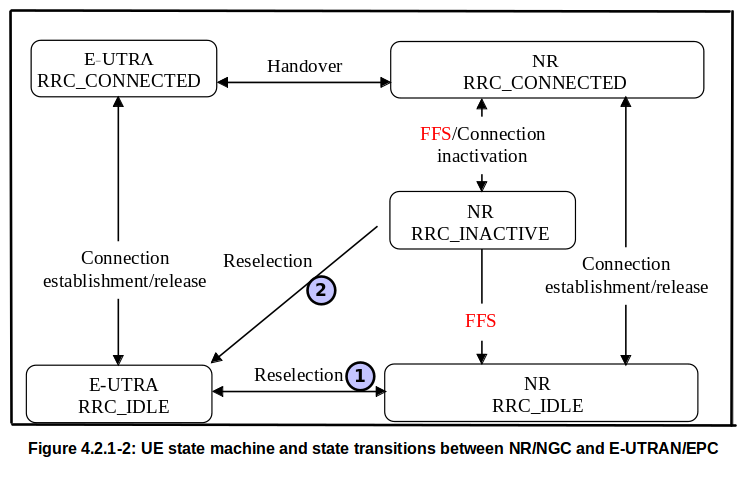
    The Radio Resource Control (RRC) state machine for New Radio (NR) is shown in Fig. 4.2.1.1

    A UE starts from RRC Idle mode when it first camps on a 5G cell. for example. This can happen immediately after the device is switched on, or it can happen after inter-system cell reselection from LTE. A UE makes the transition from RRC idle to RRC Connected by completing the RRC setup process. An RRC connection is a logical connection between the UE and the base station.

    In RRC connected mode a UE is assigned one or two C-RNTI (Cell Radio Network Temporary Identifiers). C-RNTI is used for addressing UEs when it require resource allocation from cell. A single C-RNTI is allocated when the UE is connected to a single base station. Two C-RNTIs are allocated when UE is connected using Multi-RAT Dual Connectivity (MR-DC)

    In RRC connected mode a UE is configured with at least one Signaling Radio Bearer (SRB) and usually one or more Data Radio Bearers (DRB). SRBs can be used to transfer signaling messages between the UE and the base station. Signaling messages can be related to the RRC signaling protocol or the non-access striatum (NAS) signaling protocol. The base station uses the NG Application Protocol (NGAP) to transfer NAS messages to and from the AMF. The DRB can be used to transfer application data between the UE and the base station. Base station Uses a GTP-U tunnel to transfer data to and from the UPF.

    UE has to change to RRC connected mode to register with the network, i.e. to change from RM-deregistered to RM-registered. Once a UE is registered with the network the UE will normally remain RM-registered, regardless of the RRC state. The registration process allots the UE with a temporary identity known as 5G-S-TMSI. Use of temporary identification instead of permanent identity, e.g. IMSI helps to improve security.

    UE has to change to CM-IDLE to CM-connected, the UE must change to RRC connected mode. UE is returned to the CM-IDLE Whenever a RRC connection is released. The UE remains in CM-connected until change it state from RRC Connected to RRC idle.

    A UE change from RRC Connected to RRC Inactive using the RRC Release procedure. The RRC release message includes a 'suspendConfig' parameter structure that indicates that the UE is being moved to RRC inactive instead of RRC idle. The NG signaling connection between the base station and the AMF is maintained while the UE RRC is inactive. In addition, GTP-U tunnels are maintained between the base station and UPF (one GTP-U tunnel per PDU session). UE context is also maintained by both the network and the UE

    The RRC Idle state allows the UE to return to RRC Connected and begin transferring application data or signaling messages with minimal latency. For RRC-associated signaling load is reduced relative to inactive RRCs because the UE context is already established. The RRC idle state allows the UE to reduce the battery power consumption associated with the RRC. This can be achieved with longer DRX cycles and does not require channel quality reporting.

    The AMF can request the base station to provide notifications when the UE moves between RRC connected and RRC inactive. This request can be included in the ngap 'Initial context setup request' or 'UE context modification request' messages. The base station subsequently provides updates using the NGAP 'RRC inactive Transition Report'. The AMF can use this information to adjust its observation timer with respect to the RRC status of the UE. For example, if the AMF knows that the UE is connected to the RRC it can expect a rapid response to any downlink transaction and therefore it can implement a relatively short supervision timer. If the AMF knows that the UE RRC is inactive it can expect a less rapid response to any downlink transactions as those transactions must be paginated in the UE before forwarding to the UE. The amf can thus apply a long observation timer to the UE that is RRC inactive.

    Switching between NR RRC CONNECTED <-> INACTIVE <-> IDLE State Change

    RRC CONNECTED


    NR RRC CONNECTED to INACTIVE to IDLE State Change
    UE is in CM-CONNECTED state
    UE stores Access Stratum context
    UE reads System Information
    UE monitors the Paging by PDCCH DCI using the P-RNTI
    UE is addressed using C-RNTI allocated by gNodeb
    Connected Mode DRX can be configured
    Mobility is based upon handovers
    AMF maintains NG signalling connection with gNodeb
    UPF maintains GTP-U tunnels with gNodeb
    Radio Access Network is responsible for UE reachability
    Uplink and downlink data can be transferred
    UE reports Channel State Information (CSI)
    UE monitors Control Channels for Resource Allocations
    UEs supporting CA, use of one or more SCells, aggregated with the SpCell, for increased bandwidth
    UEs supporting DC, use of one SCG, aggregated with the MCG, for increased bandwidth

    RRC INACTIVE


    switching between RRC CONNECTED and RRC INACTIVE state
    UE is in CM-CONNECTED
    UE stores Access Stratum context
    UE reads System Information
    UE monitors the Paging by PDCCH DCI using the P-RNTI
    UE monitors the PCCH for CN paging using the 5G-S-TMSI and RAN paging using the I-RNTI
    UE applies DRX for paging
    Mobility is based upon Cell Reselection
    AMF maintains NG signalling connection with gNodeb
    UPF maintains GTP-U tunnels with gNodeb
    Radio Access Network is responsible for UE reachability
    UE Performs RNA updates
    gNodeb knows the UE location with a resolution of a RAN Notification Area (RNA)
    RRCRelease  with SuspendConfig
    <Table 1.>
    RRCResumeRequest
    <Table 2.>
    RRCResumeRequest1
    <Table 3.>

    Signalling used to resume an RRC Connection at a Target eNodeb

    Figure 112. shows the signaling call flow used to resume the RRC connection at a Target gNodeb. UE initiates the process by sending either RRC Resume Request or RRC Resume Request 1. The contents of these messages are presented in Tables No. 2 or 3. The selection is based on the 'useFullResumeID' flag present in SIB1. Both messages contain I-RNTI, MAC-I and cause values. The MAC-I information element is used to authenticate the UE before the UE is re-enter to RRC Connected at source gNodeb.
    Signalling used to resume an RRC Connection at a Source eNodeb
    <Figure 112>

    RRC IDLE

    UE is in CM-IDLE state
    UE reads System Information
    UE monitors the Paging by PDCCH DCI using the P-RNTI
    UE monitors the PCCH for CN paging using the 5G-S-TMSI
    UE applies DRX for paging
    Mobility is based upon Cell Reselection
    Core Network knows UE location with resolution of Registration Area (one or more Tracking Areas)
    UE performs Registration Area updates with Core Network

    NR RRC Interaction with LTE RRC

    NR RRC is involved not only in NR but also in other radio access technology. The interaction of NR RRC and LTE RRC can be represented as follows. Here are the things to note
    1. when UE in idle state it's NR RRC IDLE can reselect to EUTRA RRC IDLE and EUTRA RRC IDLE can reselct to NR RRC IDLE.
    2. But, when UE is in NR RRC INACTIVE state, it can select to EUTRA RRC IDLE state, but EUTRA RRC IDLE state cannot reselect to NR RRC INACTIVE state.
    NR_NGC Interaction with LTE_EPC


    5G QoS

    Joni Tyagi

    Quality of Service (QoS) with 5GC Quality

    A flow in this context is a QoS flow: all Packet Data Units (PDUs) that will receive the same QoS facility in the network, are used to classify PDUs into QoS flows. Filters can be provided with 5G policy control or can be pre-configured in 5G cores.

    QoS Model General Overview

    The 5G QoS model supports the QoS flow-based framework. The 5G QoS model supports both QoS flows that require guaranteed flow bit rates and QoS flows that do not require guaranteed flow bit rates. The 5G QoS model also supports reflective QoS.
    5G Quality of Service QoS

    5G EPC vs NGCN – Bearers vs Flows

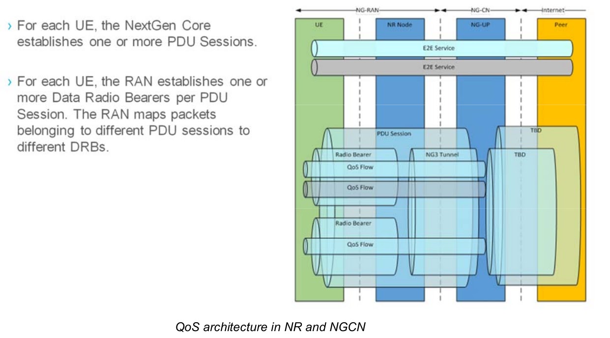
    QoS flow is the best granularity of QoS resolution in a PDU session.
    QoS flow is the best granularity of QoS resolution in a PDU session. QoS Flow ID (QFI) is used to identify QoS flows in a 5G system. User plane traffic with the same QFI within the PDU session receives the same traffic forwarding treatment (eg scheduling, admission threshold). The QFI is carried in an encapsulation header on N3 (and N9), ie without making any changes to the e2e packet header. It can be applied to various types of payloads, ie IP packets, non-IP PDUs, and PDUs with Ethernet frames. The QFI will be unique within the PDU session.

    Note: Policing of user plane traffic (eg MFBR enforcement) is not considered QoS differentiation and is carried out by the UPF at SDF level granularity.

    Each QoS flow (GBR and non-GBR) is associated with the following QoS parameters:
    • 5G QoS Indicator (5QI),
    • Allocation and Retention Priority (ARP).
    Each GBR QoS flow is associated with the following QoS parameters:
    • Guaranteed Flow Bit Rate (GFBR) - UL and DL;
    • Maximum flow bit rate (MFBR) - UL and DL;
    • Notification control.
    Two methods of controlling QoS flow are supported:
    1) For non-GBR QoS flows with standardized 5QI, the standardized 5QI value is used as QFI and the default ARP is used. In this case no additional N2 signaling is required at the time of traffic when the corresponding QoS flow starts, or;

    2) For GBR and non-GBR QoS flows, all the required QoS parameters related to QFI are sent as a QoS profile to the (R) AN in the PDU session establishment or QoS flow establishment / modification

    The QoS parameters of a QoS flow are provided to the (R)AN as a QoS profile over N2 at PDU Session or at QoS flow establishment and when 5G-RAN is used at every time the User Plane is activated. QoS parameters can be pre-configured in (R) AN for non-GBR QoS flows (ie without the need to signal over N2).

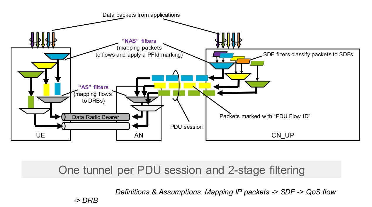
    The UE classifies and marks the UL user plane traffic based on QoS rules, that is, the linking of uplink traffic to the QoS flow. These rules can be explicitly signalled over N1 (on PDU session establishment or QoS flow establishment), preconfigured in UE or implicitly derived by UE from reflective QoS. The QoS rule consists of a QoS rule identifier, the QFI of the QoS flow, and a QoS flow template (ie the set of packet filters and the associated precedence values ​​associated with the QoS flow).

    A default QoS rule is required for every PDU session. The default QoS rule shall be the only QoS rule of a PDU session which is allowed not to have a QoS flow template. If the default QoS rule does not contain a QoS flow template, the default QoS rule defines the treatment of packets that do not match a QoS flow template of a QoS rule in a PDU session.

    The SMF allocates the QFI for each QoS flow and derives its QoS parameters from the information provided by the PCF. When applicable, the SMF provides the QFI with a QoS profile containing the QoS parameters of a QoS flow to the (R)AN. The SMF provides the SDF template (i.e. the set of packet filters associated with the SDF derived from the PCF) with the SDF preference and the corresponding QFI to the UPF enabling the classification and marking of user plane traffic. When applicable, SMF generates QoS rule (s) for QoS flows by allocating QoS rule identifiers, adding QFIs to QoS flows, and setting the QoS flow template using one or more SDF templates. QoS rules are then provided to the UE to enable classification and marking of UL user plane traffic.

    For DL traffic AN can detect which flow a received packet belongs to by looking in the encapsulation tunnel header, where the UPF has marked the packet with the QoS Flow Indicator (QFI). Information about the treatment of each flow is sent from 5GCN to AN over N2.

    UE for UL traffic marks traffic with the correct QFI based on the information received from the SMF over N1 interface. The solution will also be available for Reflective QoS where the UE marks the UL traffic based on which QFI is the DL traffic corresponding to the same flow. AN informs the UE how to send PDUs over the air (which radio bearer to use).

    Each PDU session in a session establishment is associated with a default QoS profile (a set of QoS parameters).
    • The default QoS profile is usually configured in UDM and can be authorized by PCF
    • The QoS profile indicates the treatment of all PDUs transferred within the PDU session and for which the network has not indicated PDU specific treatment.
    • The PCF can modify the default QoS profile for a PDU session at any time during the session

    QoS parameters per QoS flow:

    • 5G QoS indicator (5QI)
    • Allocation and Retention Priority (ARP)
    • Maximum Flow Bit Rate
    • Guaranteed Flow Bit Rate
    • Notification control. Controls whether notification should be made if the QoS targets are no longer fulfilled for a QoS flow

    QoS parameters per PDU session

    • Aggregated session maximum bitrate (UL and DL) for all QoS flows of a PDU session that do not require a guaranteed flow bit rate.
    • Aggregated UE maximum bitrate (UL and DL) for all QoS flows and sessions of the UE that do not require a guaranteed flow bit rate.
      5G Evolved QoS
    • Multiplexing flow within a PDU (PDN) session tunnel
    • Flow identities indicates on the QoS profile
    • The DRB is mapped to the PDU session tunnel
    • Multiple DRBs possible per PDU session tunnel
    • The PDCP header on UL carries the Flow Id to map to DSCP on UL
    • Each packet have the DL Flow ID

    5G Definitions & Assumptions NextGen Core network
    Services are mapped to the Service Data Flow (SDF)

    SDF, which consists of the following, assigned QoS profile:
    • SDF priority
    • Maximum bitrate per SDF:
    • Bitrate required per SDF
    • Delivery characteristic per SDF
    • Network behavior per service data flow
    The SDF is mapped to a QoS flow and the packet is marked with a QoS flow Id
    5G QoS Mapping IP packets

    QoS flow, which contains the following parameters, a QoS profile is assigned:

    • QoS flow priority
    • Maximum bitrate per QoS flow
    • Bitrate required per QoS flow
    • Delivery characteristic per QoS flow
    • Network behavior per QoS flow

    The SDF of the same IP-CAN session can be considered as the SDF Aggregate

    • All SDFs should have the same QCI / ARP
    • GBR / MBR is summarized in GBF SDFs when multiplexing GBR SDFs

    SDF Aggregates are mapped to UL/DL Packet Filters/EPS Bearers

    • 1:1 relation – an SDF Aggregate uniquely defines the EPS Bearer
    • Bearer QoS profile (QCI, ARP, GBR, MBR), per-UE parameter AMBR and subscription parameter RFSP signaled over S1

    QoS Flow Id is mapped to Radio Bearers

    • N: 1 relation

    Based on pre-configured nodes, via OSS-RC

    • Standardized QCI Characteristics
    • Resource Type
    • GBR / Non-GBR
    • Packet Delay Budget (PDB)
    • Packet Loss Rate (PLR)
    • Priority
    • Priority between bearers when target PDB cannot be met (by bearers
    • competing for the same resource)
    • Other parameters set in OSS, by operator in MOM