• Vision
  • About us
  • LTE RANDOM ACCESS PROCEDURE

    Jitendra Kumar

    RAP(Random Access Procedure)
    Random Access procedure is essential part of for LTE protocol communication and used for getting the grant of Uplink resources for sending RRC message first time so that UE will attached to Network. So Here I tried to provide you RAP step wise step.
    lte-Random-Access-Procedure
    RA Procedure Messages with Timers

    1.     UE MAC(refer Ans 1) select a preamble out of the available 64 preamble randomly(0-64) either contention based or Non contention Based.
    2.     UE MAC gives this preamble to UE physical for dispatch.
    3.     UE MAC tells UE physical about which PRACH resource(refer Ans 23) should be used for preamble sending.
    4.     UE Phy transmit the preamble on the selected PRACH resources.
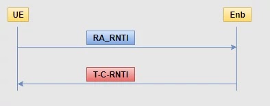
    5.     Before Transmission UE physical calculate RA-RNTI (refer Ans 36).
    6.     eNB physical received preamble on PRACH resource and calculate RA-RNTI first.
    7.     eNB phy forward the preamble to eNB MAC.
    8.     eNB MAC allocate UL resource for the UE and this information forwarded to UE.
    9.     eNB MAC prepares a message called RAR(Random Access Response) with the following detail:
    a.     Preamble ID
    b.     PUSCH PRB
    c.     T-C-RNTI
    d.     Timing Advance
    lte-rnti
    RNTIs


    10.  This RAR must be sent to UE on PDSCH channel by reserving PRB.
    11.  eNB MAC allocate a PRB for the UE on PDSCH and gives these details [RAR+PDSCH PRB] to eNB physical.
    12.  First eNB phy have to send the PDSCH PRB reservation detail to UE on the PDCCH channel against RA-RNTI.
    13.   eNB PHY pack RAR info on PDSCH PRB and transmit it.
    14.  UE PHY always listening to PDCCH to get to know that there is any PRB allocates against his RA-RNTI on PDSCH.
    15.  UE PHY download the specified PRB and decode the info and send it to UE MAC.
    16.  UE MAC received RAR which contain many detail .
    17.  UE MAC verify the preamble id if matched than UE MAC decided to send “msg3”.
    18.  “msg3” is nothing but a RRC connection request message.
    19.  UE MAC send msg3 to UE PHY along with PUSCH PRB used for transmit.
    20.  Also MAC tells physical layer about how much timing advance must be applied before Tx.
    21.  UE PHY Tx “msg3” by coding into PUSCH PRB indicated.
    22.  eNB PHY received this and send to eNB MAC.
    23.  eNB MAC will perform the below task:
    a.     Send ACK in the name of CRI(refer Ans 19) to UE that I have received msg3.
    b.     Send msg3 to higher layer.
    24.  eNB reserve a PRB for the UE on the PDSCH against T-C-RNTI to send CRI and send it.
    25.  UE MAC compare the CRI received with Tx msg3, if equal than RAP is successful otherwise failed.

    5GC Architecture

    Joni Tyagi

    The 5G SA Core architecture is describe in the following figure.

    5G-Core-Architecture-5g-core-5g-core-network-5g-core-network-architecture
    The SA Architecture
    * The SA architecture can be seen as the "full 5G deployment", not needing any part of a 4G network to operate.
    * The NR base station (logical node "gNB") connects with each other via the Xn interface, and the Access Network (called the "NG-RAN for SA architecture") connects to the 5GC network using the NG interface.
    * The continuation of this section refers to the SA architecture, the NSA being addressed in a subsequent, dedicated, section.

    Overview of the Core Network

    * In the SA deployment option, the 5G System (5GS) is composed of the User Equipment, the Access Network (including the "New Radio" or NR) and the Core Network (5GC or 5GCN).
    * The service requirements, as presented in the previous clause, were used as a basis to define the architecture. The architecture specification (also called, Stage 2) started with a preliminary study in TR 23.799, also called "NextGen TR", before being fully specified in TS 23.501, TS 23.502 and TS 23.503.
    * The 5GC architecture relies on a so-called "Service-Based Architecture" (SBA) framework, where the architecture elements are defined in terms of "Network Functions" (NFs) rather than by "traditional" Network Entities. Via interfaces of a common framework, any given NF offers its services to all the other authorized NFs and/or to any "consumers" that are permitted to make use of these provided services. Such an SBA approach offers modularity and reusability.
    * The basic (SA, non-roaming) 5G System architecture is shown below (figure introduced by the editor):
    5G-Core-Architecture-5g-core-5g-core-network-5g-core-network-architecture
    Overview of the 5G System architecture
    At this stage, only the following essential Network Functions and elements are highlighted here:

    -    The User Equipment (UE);

    -    The (Radio) Access Network [(R)AN];

    -    The User Plane Function (UPF), handling the user data;

    -    The (external) Data Network (DN);

    -    Some remarkable Network Functions (NFs):

    -    The Application Function (AF), handling the application(s);

    -    The Access and Mobility management Function (AMF), that accesses the UE and the (R)AN;

    -    The Session Management Function (SMF) that accesses the UPF.

    The other NFs are introduced later.

    * The SBA (Service Based Architecture) approach enables a virtualized deployment. Indeed, a Network Function instance can be deployed as fully distributed, fully redundant, stateless and/or fully scalable. Several Network Function instances can be present within a same NF set. Conversely, the services can be provided from several locations.
    * In other words, when the services of a specific NF are invoked, this virtualization enables to route the UE's messages to any capable entity (within a pre-defined set of equivalent NFs).
    * This provides resiliency: any specific instance of the NF can e.g. be turned off for planned maintenance, and there will be auto-recovery without any service disruption.

    Overview of the Access Network

    As a first approach, the architecture of the 5G AN is extremely simple since it consists in one single entity, the gNB, which connects to the 5G CN via the NG interface. It may also connect to another gNB via the Xn interface and/or to the 4G's eNB via the X2 interface, as shown below in the editor-proposed picture inspired from TS 38.401 and TS 38.420. It also connects to the UE via the NR interface, not shown on the figure. Note that this AN architecture is rather similar in its principle to what was developed for LTE with the eNB, as can be seen in TS 36.401.
    5G-Core-Architecture-5g-core-5g-core-network-5g-core-network-architecture
    Overview of the AN interfaces

    References for 5GS

    The main specifications for the 5G System are:
    [1]     TS 23.501, "System Architecture for the 5G System"
    [2]     TS 23.502, "Procedures for the 5G System"
    [3]     TS 23.503, "Policy and Charging Control Framework for the 5G System"
    [4]     TR 23.799 "Study on Architecture for Next Generation System"
    [5]     TS 38.401 " NG-RAN; Architecture description"
    [6]     TS 38.420 " NG-RAN; Xn general aspects and principles"
    [7]     TS 36.401 "Evolved Universal Terrestrial Radio Access Network (E-UTRAN); Architecture description"

    5G Random Access Procedure

    Joni Tyagi

    5G Random Access Procedure:


    ·        Why Random Access Procedure Require:
    §  Used for UE UL Synchronization between UE to Network
    §  Require UL Resources for sending Msg3 or data stored in buffer
    §  UE Initial access from RRC_IDLE
    §  Random Access Procedure is always initiated by UE MAC Layer
    §  RRC Connection and RRC Re-establishment procedure
    §  During Handover Time
    §  During RRC_CONNECTED DL or UL data arrival when UE have UL synchronization
    §  Transition from RRC_Idle to RRC_Active State;
    §  To establish time alignment at Secondary Cell addition;
    §  Request for Other System Information
    And Beam failure recovery.

    ·        How many Types of Random Access Procedure:

    Contention Based and Non-Contention Based

    Random Access Procedure types are similar to LTE procedure.
    Contention Based RAP: - Collision possible on PRACH Transmissions from several UE’s.
    5G-Random-Access-Procedure-Contention-based

    §  Non Contention Based RAP: - Collisions will be avoided as Network allocates special pattern and special PRACH Resources.
    5G-Random-Access-Procedure-non-contention-based

    *UE MAC Randomly select a preamble from a 64 preambles broadcast in PDCCH by network. How?
    Preamble Sequence Generation

    In UE MAC Zadoff-chu sequence generation is used for generate preamble and it have a property to convert actual no. into complex no. (The complex no. having different angular values)
    random-access-Zadoff-chu-sequence

    From which frequency domain sequence generated 
    random-access-Zadoff-chu-sequence

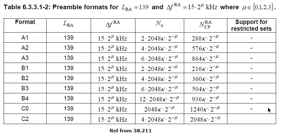
    Where LRA = 839 or LRA = 139 depending on the PRACH preamble format define below:
    PRACH-Preamble-formats

    5g-PRACH-Preamble-formats
    Long Preamble Features:

    §  A long preamble with 1.25 kHz numerology holds 6 resource blocks in the frequency domain, while a preamble with 5 kHz numerology holds 24 resource blocks.
    §  The Long preambles are based on a sequence length is L = 839
    §  Sub-carrier spacing can be 1.25 Khz or 5 Khz for long preamble
    §  Numerology used for long preambles is different from any other NR broadcast
    §  Origin of long preambles partly from preamble used for LTE
    §  Long preambles can only be used for FR1 frequency bands that are less than 6000 Mhz (6 Ghz)
    §  There are 4 different formats for long preface names format # 0, format # 1, format # 2 and format # 3
    §  NR preamble formats 0 and 1 are similar to LTE preamble formats 0 and 2
    The above 64 preambles are using, have 4 formats and are using in generally Numerology 0 which is similar with 4G. But in 5G we have 4 others Numerologies which are used for higher bands. So total 13 different preambles formats are used in 5G.

    The below table shown FR2 preamble formats:
    fr2-PRACH-Preamble-formats

    Short Preamble Features:
    §  The Short preambles are based on a sequence length L is = 139
    §  The sub-carrier spacing for the short-preamble is aligned with the normal NR sub-carrier spacing i.e. 15 KHz, 30 KHz, 60 KHz and 120 KHz.
    §  Short preambles use subcarrier spacing of the following:
    §  In case of operation below 6 GHz (FR1) of 15 KHz or 30 KHz.
    §  60 Khz or 120 Khz in case of operation in high NR frequency band (FR2).
    §  A short preamble holds 12 resource blocks in the frequency domain regardless of numerology
    §  Short preambles are generally shorter than longer preambles and often feature only a few OFDM symbols.
    §  Short preamble formats are designed such that the end of each OFDM symbol acts as a CP for the next OFDM symbol and the length of the preamble OFDM symbol is equal to the data of the OFDM symbol

    §  In most cases it is therefore possible that multiple preamble transmissions within the same RACH slot (opportunity) are collide in a time. In other words, for short previews there may be multiple RACH opportunities in a single RACH slot in the frequency domain as well as in the time domain.

    §  The 5G NR supports a mix of "A" and "B" formats to enable additional formats such as A1 / B1, A2 / B2, and A3 / B3.
    §  The short Preamble formats are the same except for some short cyclic prefixes for the A and B, B formats.
    §  The preamble formats B2 and B3 are always used in combination with the corresponding A formats (A2 and A3)
    §  Micro-preambles are designed to target small / common cell and indoor deployment scenarios.
    §  Short preambles allow gNB receivers to use the same fast Fourier transform (FFT) for data and random-access premature detection.
    §  These preambles are composed of several small OFDM symbols per second preamble, making them more robust against periodic channels and frequency errors.
    §  The short preambles supports analog beam sweeping during PRACH reception, so that the same preamble can be obtained with different beams at GBB
    *After that UE mac gives this preamble’s to ue’s physical for dispatch via PRACH resources:
    5g-PRACH-resources
    5g-PRACH-resources
    5g-PRACH-resources
    5g-PRACH-resources-formats
    5g-PRACH-resources-info

    *Now UE physical layer calculate RA_RNTI:
    RA-RNTI= 1 + s_id + 14 × t_id + 14 × 80 × f_id + 14 × 80 × 8 × ul_carrier_id
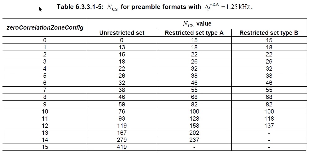
    Zero Correlation Zone:
    5g-zero-correlation-zone-config
    nr-zero-correlation-zone-config
    Root Sequence:
    5g-Root-Sequence
    nr-Root-Sequence
    *RRC layer configure the following parameters for RAP:


    - prach-ConfigurationIndex: Provide the set of PRACH occasions for the transmission of the Random Access Preamble
    - preambleReceivedTargetPower: initial Random Access Preamble received power;
    - rsrp-ThresholdSSB: This RSRP threshold is used for the selection of the SSB and corresponding Random Access Preamble and PRACH occasion. If the Random Access procedure is initiated for beam failure recovery, rsrp-ThresholdSSB used for the selection of the SSB within candidateBeamRSList refers to rsrp-ThresholdSSB in BeamFailureRecoveryConfig IE;
    - rsrp-ThresholdCSI-RS: This RSRP threshold is used for the selection of CSI-RS and corresponding Random Access Preamble and PRACH occasion. If the Random Access procedure is initiated for beam failure recovery, rsrp-ThresholdCSI-RS shall be set to a value calculated by multiplying rsrp-ThresholdSSB in BeamFailureRecoveryConfig IE by powerControlOffset as specified in TS 38.214 [6];
    - rsrp-ThresholdSSB-SUL: This RSRP threshold is used for the selection between the NUL carrier and the SUL carrier;
    - candidateBeamRSList: list of reference signals (CSI-RS and/or SSB) is used to identifying the candidate beams for recovery and the associated Random Access parameters;
    - powerControlOffset: a power control offset present between rsrp-ThresholdSSB and rsrp-ThresholdCSI-RS and it’s used when the Random Access procedure is initiated for beam failure recovery.
    - powerRampingStep: the power-ramping factor is used to increase preamble transmit power.
    - powerRampingStepHighPriority: in case of differentiated Random Access procedure the power-ramping factor is used.
    - scalingFactorBI: The scaling factor is used for differentiated Random Access procedure;
    - ra-PreambleIndex: nothing but Random Access Preamble;
    - ra-ssb-OccasionMaskIndex: defines PRACH occasion(s) associated with an SSB in which the MAC entity may transmit a Random Access Preamble (see spec 36.321 subclause 7.4).
    - ra-OccasionList: It defines PRACH occasion’s associated with a CSI-RS in which the MAC entity may transmit a Random Access Preamble;
    - ra-PreambleStartIndex: the starting index of Random Access reamble(s) for on-demand SI request;
    - preambleTransMax: used to count maximum number of Random Access Preamble transmission.
    The UE MAC entity handles the RAP procedure in transport Channels called Random Access Channel
    * When UE is configured with SCG (Secondary Cell Group) than 2 MAC entities configured 1st for MCG (Master Cell Group) and 2nd for SCG.
    *The timers and parameters are used in each MAC entities are configured independently else specified.
    *The Serving Cells, CRNTI, Radio Bearers, Logical CHannels, Upper and Lower layer entities, LCGs, and HARQ entities considered by each MAC entity.
    *If the MAC entity is configured with 1’s or more SCells (Secondary Cells), there are multiple DL-SCH and there may be multiple ULSCH as well as multiple RACH have per MAC entity.
    * And 1’s DLSCH, 0’s or 1’s UL-SCH and 0’s or 1’s RACH for each Secondary Cell
    *Or 1’s DL-SCH, 1’s UL-SCH, and 1’s RACH on the Special Cell.
    ** If MAC entity is not configured with any Secondary Cell, than there is 1’s DL-SCH, 1’s UL-SCH, and 1’s RACH per MAC entity.