• Vision
  • About us
  • Showing posts with label 5G Architecture. Show all posts
    Showing posts with label 5G Architecture. Show all posts

    5GC Architecture

    Joni Tyagi

    The 5G SA Core architecture is describe in the following figure.

    5G-Core-Architecture-5g-core-5g-core-network-5g-core-network-architecture
    The SA Architecture
    * The SA architecture can be seen as the "full 5G deployment", not needing any part of a 4G network to operate.
    * The NR base station (logical node "gNB") connects with each other via the Xn interface, and the Access Network (called the "NG-RAN for SA architecture") connects to the 5GC network using the NG interface.
    * The continuation of this section refers to the SA architecture, the NSA being addressed in a subsequent, dedicated, section.

    Overview of the Core Network

    * In the SA deployment option, the 5G System (5GS) is composed of the User Equipment, the Access Network (including the "New Radio" or NR) and the Core Network (5GC or 5GCN).
    * The service requirements, as presented in the previous clause, were used as a basis to define the architecture. The architecture specification (also called, Stage 2) started with a preliminary study in TR 23.799, also called "NextGen TR", before being fully specified in TS 23.501, TS 23.502 and TS 23.503.
    * The 5GC architecture relies on a so-called "Service-Based Architecture" (SBA) framework, where the architecture elements are defined in terms of "Network Functions" (NFs) rather than by "traditional" Network Entities. Via interfaces of a common framework, any given NF offers its services to all the other authorized NFs and/or to any "consumers" that are permitted to make use of these provided services. Such an SBA approach offers modularity and reusability.
    * The basic (SA, non-roaming) 5G System architecture is shown below (figure introduced by the editor):
    5G-Core-Architecture-5g-core-5g-core-network-5g-core-network-architecture
    Overview of the 5G System architecture
    At this stage, only the following essential Network Functions and elements are highlighted here:

    -    The User Equipment (UE);

    -    The (Radio) Access Network [(R)AN];

    -    The User Plane Function (UPF), handling the user data;

    -    The (external) Data Network (DN);

    -    Some remarkable Network Functions (NFs):

    -    The Application Function (AF), handling the application(s);

    -    The Access and Mobility management Function (AMF), that accesses the UE and the (R)AN;

    -    The Session Management Function (SMF) that accesses the UPF.

    The other NFs are introduced later.

    * The SBA (Service Based Architecture) approach enables a virtualized deployment. Indeed, a Network Function instance can be deployed as fully distributed, fully redundant, stateless and/or fully scalable. Several Network Function instances can be present within a same NF set. Conversely, the services can be provided from several locations.
    * In other words, when the services of a specific NF are invoked, this virtualization enables to route the UE's messages to any capable entity (within a pre-defined set of equivalent NFs).
    * This provides resiliency: any specific instance of the NF can e.g. be turned off for planned maintenance, and there will be auto-recovery without any service disruption.

    Overview of the Access Network

    As a first approach, the architecture of the 5G AN is extremely simple since it consists in one single entity, the gNB, which connects to the 5G CN via the NG interface. It may also connect to another gNB via the Xn interface and/or to the 4G's eNB via the X2 interface, as shown below in the editor-proposed picture inspired from TS 38.401 and TS 38.420. It also connects to the UE via the NR interface, not shown on the figure. Note that this AN architecture is rather similar in its principle to what was developed for LTE with the eNB, as can be seen in TS 36.401.
    5G-Core-Architecture-5g-core-5g-core-network-5g-core-network-architecture
    Overview of the AN interfaces

    References for 5GS

    The main specifications for the 5G System are:
    [1]     TS 23.501, "System Architecture for the 5G System"
    [2]     TS 23.502, "Procedures for the 5G System"
    [3]     TS 23.503, "Policy and Charging Control Framework for the 5G System"
    [4]     TR 23.799 "Study on Architecture for Next Generation System"
    [5]     TS 38.401 " NG-RAN; Architecture description"
    [6]     TS 38.420 " NG-RAN; Xn general aspects and principles"
    [7]     TS 36.401 "Evolved Universal Terrestrial Radio Access Network (E-UTRAN); Architecture description"

    5G Protocol Stack

    Joni Tyagi

    5G Protocol Stack:

    The 5G protocol stack is similar to the 4G protocol stack, but has some changes. If I talk about the changes, what kind of changes happen in 5G, then let me tell you that some new components have been introduced and 4G has some limitations, which have been overcome in 5G, So obviously some changes are needed. Therefore in 5g protocol stack the only one new layer is introduced is SDAP layer (in user plane only); present between rrc and pdcp and other protocols are same.
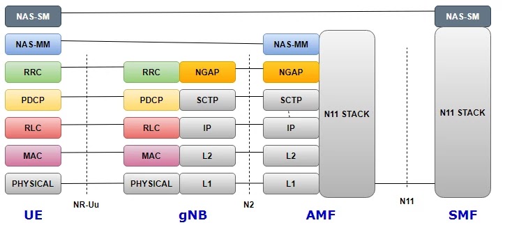
    So here I am sharing the 5G control plane protocol stack here and user plane below:
    5G-Control-Plane-Protocol-Stack

    5G Control Plane Protocol Stack; between the UE and the 5G Core:

    First I am sharing the details of 5G control plane; In the picture above you will get an idea of ​​ue's protocol stack in 5g core components, 


    In below picture define brief detail of NAS layer and the lower layer is mentioned in the picture, are RRC; and transport layers PDCP, RLC, MAC, PHYSICAL layer. More importantly, the AMF has only the NAS layer, the transport layers are absent in the AMF.
    5G-Control-Plane-Protocol-Stack-between-the-UE-and-the-5G-Core
    A single N1 NAS signaling connection is used for each received entry to which the UE is attached. The single N1 endpoint is placed in the AMF. Single N1 NAS signaling connections are used for both registration management and connection management (RM / CM) and for SME-related messages and tactics for UEs.
    The NAS protocol on N1 includes the NAS-mobility management and NAS-session management components.
    There is more than one case of protocol between the UE and the core network function (excluding AMF) that needs to be carried over the N1 through NAS-MM protocol. Such examples include:
    - Session Management Signalling.
    - SMS.
    - UE Policy.
    - LCS.
    RM/CM NAS messages in NAS-MM and other forms of NAS messages (e.g. SM), as well as the corresponding methods, are decoupled.
    The NAS-MM supports generic talents:
    => NAS techniques that terminate on the AMF. This includes:
    => Registration management and connection management with UE handles state machines and technologies, including NAS shipping; AMF supports the following skills:
    -- Decide whether to just accept the RM/CM a part of N1 signalling in the course of the RM/CM strategies without thinking about probable mixed different non NAS-MM messages (e.g., SM) inside the same NAS signalling contents;
    -- Know if one NAS message must be routed to every other NF (e.g., SMF), or domestically processed with the NAS routing capabilities inside at some stage in the RM/CM procedures; 
    -- Provide a secure NAS signalling connection (integrity protection, ciphering) between the UE and the AMF, together with for the delivery of payload;
    -- Provide get right of entry to control if it applies;
    -- It is viable to transmit the different form of NAS message (e.g., NAS SM) together with an RM/CM NAS message with the aid of helping NAS shipping of different varieties of payload or messages that don't terminate on the AMF, i.e. NAS-Session Management, SMS, User Equipment Policy and LCS between the UE and the AMF. This includes:
    -- Information approximately the Payload type;
    -- Additional Information for forwarding purposes
    -- The Payload (e.g. The SM message within the case of SM signalling);
    -- There is a Single NAS protocol that applies on both 3GPP and non-3GPP get entry to. When an UE is served via a single AMF whilst the UE is attached over a couple of (3GPP/Non 3GPP) accesses, there is a N1 NAS signalling connection in line with get admission to.
    Security of the NAS messages is provided based totally on the security context installed among the UE and the AMF.

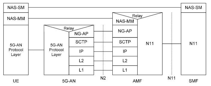
    5G-R(AN) and the AMF Control Plane:

    5G-AN-and-the-AMF-Control-Plane
    Figure 1 5G-AN and the AMF Control Plane

    -          NG-AP (Application Protocol): Is a Application Layer Protocol between the 5G-AN node and the AMF. NG-AP.
    -          Stream Control Transmission Protocol (SCTP): This protocol ensures transport of signalling messages among AMF and 5G-AN node (N2). SCTP.

    5G-R(AN) and the SMF Control Plane via AMF:

     5G-R(AN)-and-the-SMF-Control-Plane-via-AMF
    -          N2 SM information: This is the subset of NG-AP statistics that the AMF transparently relays among the AN and the SMF, and is included inside the NG-AP messages and the N11 associated messages.

    Control Plane Between UE to 5G-AN and AMF: 

    Control-Plane-Between-UE-to-5G-AN-and-AMF
    Legend:
    - NAS-MM: The NAS protocol for MM capability supports registration management capability, connection management capability and user plane connection activation and deactivation. It is also responsible of ciphering and integrity safety of NAS signalling.
    - 5G-AN Protocol layer: This set of protocols/layers relies upon on the 5G-AN. In the case of NG-RAN, the radio protocol among the UE and the NG-RAN node (eNodeB or gNodeB) is laid out.

    Control Plane Between UE to 5G-AN and AMF to SMF: 

    Control-Plane-Between-UE-to-5G-AN-and-AMF-to-SMF

    The NAS-SM helps the coping with of Session Management among the UE and the SMF.
    The SM signalling message is handled, i.e. Created and processed, inside the NAS-SM layer of UE and the SMF. The content material of the SM signalling message isn't always interpreted with the aid of the AMF.
    The NAS-Mobility Management layer handles the Session Management signalling is as follows:
    -- For transmission of SM signalling:
    - The NAS-MM layer creates a NAS-MM message, which include protection header, indicating NAS transport of SM signalling, additional data for the receiving NAS-MM to derive how and where to forward the SM signalling message.
    -- For reception of SM signalling:
    - The receiving NAS-MM techniques the NAS-MM part of the message, i.e. plays integrity check, and translates the additional statistics to derive how and wherein to derive the SM signalling message.
    The SM message part shall encompass the PDU Session ID.

    5G User Plane Protocol Stack:
    5G-User-Plane-Protocol-Stack

    5G-User-Plane-Protocol-Stack-between-UE-to-UPF
    -        PDU layer: This layer corresponds to the PDU made between the UE and the data network (DN) above the PDU session. When the PDU session type is IPv4 or IPv6 or IPv4v6, it matches the IPv4 packet or IPv6 packet or each of them; When the PDU session type is Ethernet, it matches the Ethernet frame; e.t.c
    -        GPRS Tunneling Protocol (GTP-U) for User Plane: This protocol supports visitors to various PDU sessions (possibly corresponding to unique PDU session types) with the help of user records (i.e between 5G-AN nodes) for N3 is Does, (UPF) inside the backbone network. GTP will face all rejected user PDUs. This corresponds to the PDU session level. This layer carries forward the notation associated with the QoS flow.
    -        5G Encapsulation: This layer supports separate PDU sessions on N9 (all corresponding to a unique PDU session type) (such as between specific UPFs of 5G). This corresponds to the PDU session level. This layer contains notation associated with QoS flow.
    - 5G-AN protocol stack: This set of protocols/layers depends at the AN:
    -          When the 5G-AN is a 3GPP NG-RAN, these protocols/layers are described in TS 38.401 [42]. The radio protocol among the UE and the 5G-AN node (eNodeB or gNodeB) is laid out in TS 36.300 [30] and TS 38.300 [27].
    -          When the AN is an Untrusted non 3GPP get entry to to 5GC the 5G-AN interfaces with the 5GC at a N3IWF defined in clause 4.3.2 and the 5G-AN protocol stack is defined in clause 8.3.2.
    - UDP/IP: These are the main communication protocols.
    -          NOTE 1: The wide variety of UPF inside the facts route is not constrained through 3GPP specifications: there can be inside the information path of a PDU Session 0, 1 or multiple UPF that don't help a PDU Session Anchor capability for this PDU Session.
    -          NOTE 2: The "non PDU Session Anchor" UPF depicted in the Figure.
    -          NOTE 3: The N9 interface can be intra-PLMN or inter PLMN (in the case of Home Routed deployment).
    If there's an UL CL (Uplink Classifier) or a Branching Point (each described in clause 5.6.4) inside the data direction of a PDU Session, the UL CL or Branching Point acts because the non PDU Session Anchor UPF. In that case there are a couple of N9 interfaces branching out of the UL CL / Branching Point every main to extraordinary PDU Session anchors.
    -          NOTE 4: Co-vicinity of the UL CL or Branching Point with a PDU Session Anchor is a deployment option.